how to read one line electrical drawings
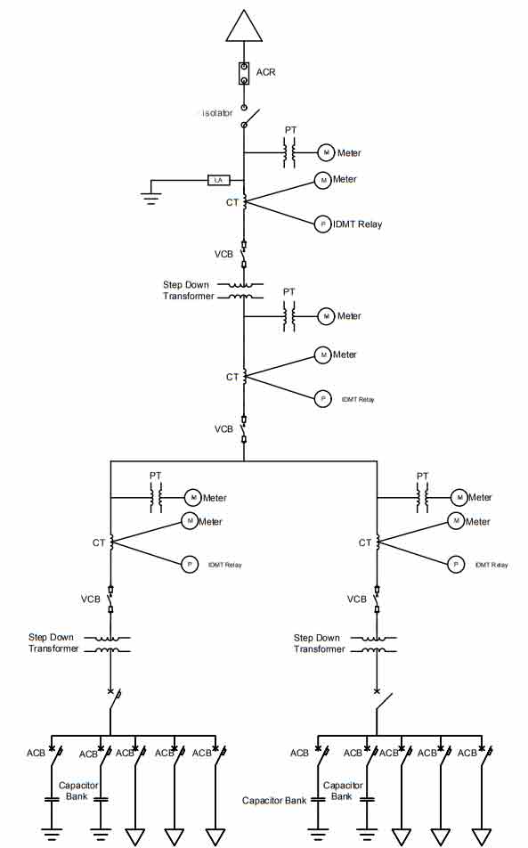
A shop drawing is a drawing or set of drawings produced by the contractor supplier manufacturer subcontractor consultants or fabricator. The one-line diagram is similar to a block diagram except that electrical elements such as switches circuit breakers transformers and capacitors are shown by standardized schematic symbols.

Pin By Cira Brown On Technical Drawing Drafting Electrical Single Line Diagram Line Diagram Electrical Symbols
Examples of these include.
. Whether that be walls in a house or the space between wiring in an electrical outlet. Read the dimension lines. Go for a resume objective.
When the current passes through the lamp it will produce light. This setting also allows lines to connect to shapes. Protective relays utilizing voltage are usually connected phase-to-phase so the transformers are normally rated 120 V line-to-line.
The line settings will help you draw your circuits. Shop drawings are typically required for prefabricated components. Scale of Reflected Ceiling Plans.
Thin Continuous Line _____ A thin continuous line could be a straight or curved line but the main point to remember is this. Apply electrical engineering design concepts to product development. In Electrical and Electronics Engineering we use different types of drawings or diagrams to represent a certain electrical system or circuitThese electrical circuits are represented by lines to represent wires and symbols or icons to represent electrical and electronic componentsIt helps in better understanding the.
The lines center point is broken and here you will see the dimension ie. To be able to read electrical as well as other types of drawings one must become familiar with the meaning of symbols lines and abbreviations used on the. This sheet sheets shows the location of the electrical circuits panel boxes and fixtures throughout the building as well as switchgears subpanels and.
In power engineering a single-line diagram SLD also sometimes called one-line diagram is a simplest symbolic representation of an electric power system. How to Read A Electrical Drawing 1. It is a tiny thin line with no dot or dashes within it.
These Drawings Are Produced With Constructibility In Mind. An antenna is a straight line with three small lines branching off at its end much like a real antenna. If the Allow Lines to Join option is selected these connected lines will become one continuous line.
Power-riser diagrams to show the service-entrance and panelboard components. The electrical drawings are numbered beginning with E. A Thin Continuous Line is used for representing the followings.
A single line in the diagram typically corresponds to more than one physical conductor. In a direct current system the line includes the supply and return paths in a three-phase system the line represents all three. A resistor will be represented with a series of squiggles symbolizing the restriction of current flow.
This program is the continuation of the Electrical Engineering Technician program and is open. Fabrication Drawings As One Can Imagine These Drawings Are Produced By The Person Or Company Who Will Actually DO The Fabricating. Reflected ceiling plans should be drawn at the same scale as the floor plansDepending on the complexity of the project and ceiling treatment the most common scale for residential and small commercial projects is i 1-0 150 metric and V8 1-0 1100 metric for large commercial projects.
While builders dont need to understand everything in the MEP plans builders should be aware of how these systems will. If youre an experienced electrical engineer writing a senior electrical engineer resume use a resume summary. Writing a fresher electrical engineering resume.
Only one phase is shown b and c phases are duplicated with secondaries connected as in a. Control wiring schematic and single-line diagrams. Taps may be provided to obtain either 693 V or 120 V line-to-neutral.
The diagram below shows the various types of line their description and general application. Translate customer technical and legal requirements into engineering designs. Heating and air-conditioning systems plumbing electrical outlets and wiring including lighting and other mechanical systems are typically detailed in MEP mechanical electric plumbing plans and installed by specialists in their field.
Highlight your career progress and skills set. A lamp is usually represented as a circle with a cross inside it. Different Types of Electrical Diagrams and Drawing.
Here are some examples of electrical engineering job responsibilities. If the Allow Lines to Link option is selected in the SmartPanel the lines will neatly snap to each other and can move as a unit while still remaining separate. Elevators structural steel trusses pre-cast concrete windows appliances cabinets air handling units and millwork.
For example a switch will be a break in the line with a line at an angle to the wire much like a light switch you can flip on and off. They are drawn as short solid lines with arrowheads on each end. Dimension lines show you the distance between any two locations in a drawing.
Advance your skillsets for a career in the electrical engineering technology field. PIDs or Piping and Instrumentation Diagrams to give them their full name are schematic representations of pipelines equipment instrumentation and control systems found in process environments such as Oil Refineries Chemical Plants Paper Mills and Cement Plants etc. In the Electrical Engineering Technology Ontario College Advanced Diploma program you use state-of-the-art facilities to gain the knowledge and experience necessary to enter the electrical engineering field.
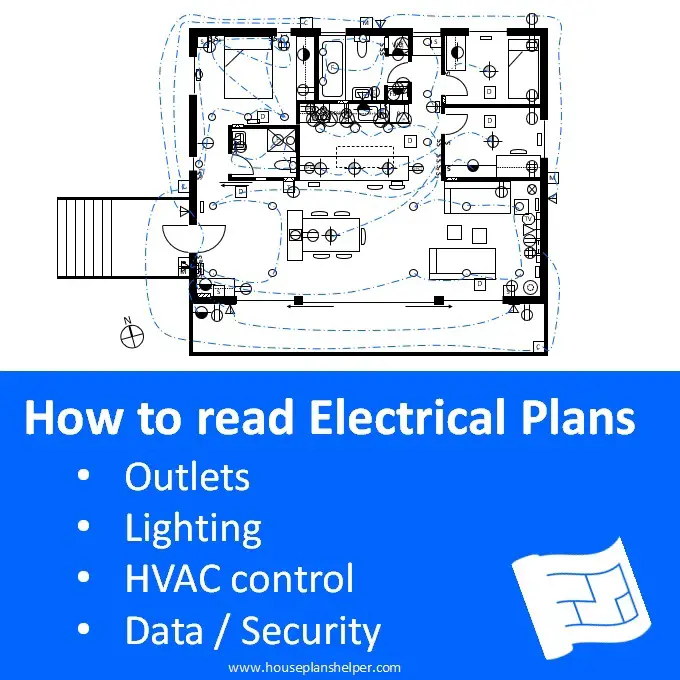
Produce electrical engineering designs and drawings eg PCB routinglayout. Whichever one you choose remember. Read the electrical plan.
A one-line diagram or single-line diagram is a simplified notation for representing an electrical system. Electrical engineering job responsibilities. In this article we will learn how to read PID drawings on a daily basis.
Schedules notes and large-scale details on construction drawings. Familiarize with Standardized Electrical Symbols Knowing the meanings of basic electrical symbols in your electrical drawing will help you quickly understand and troubleshooting the circuit. For The Most Part They Take Into Account Actual Products To Be Used Verified Field Dimensions Final New Dimensions The Actual Details On The Job.
Show what youve already learned and what you can offer your employer.
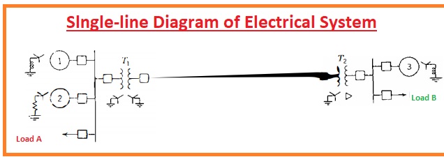
Single Line Or One Line Diagram Electrical Power System The Engineering Knowledge

How To Read Electrical Drawing Edrawmax

Electrical Wiring Diagram And Electrical Circuit Diagram Difference Etechnog
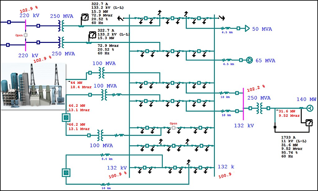
Electrical Single Line Diagram Electrical One Line Diagram Etap
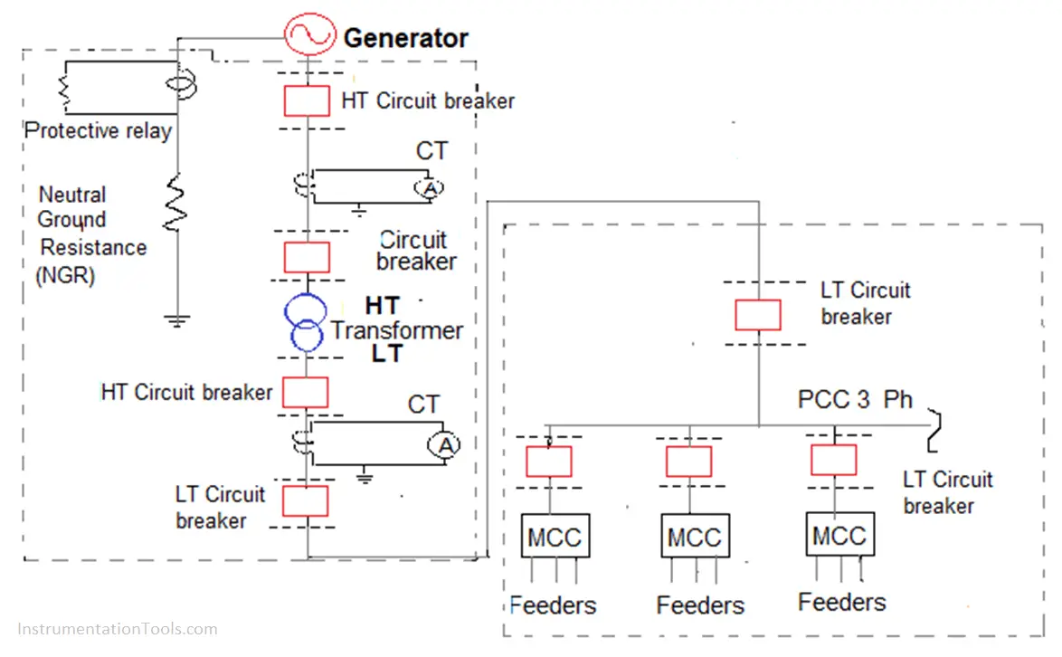
Single Line Diagram Inst Tools
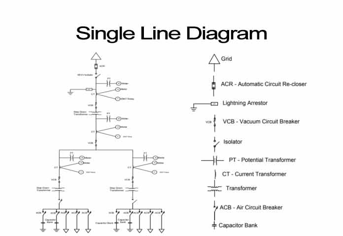
Basic Concepts About Single Line Diagrams Power System
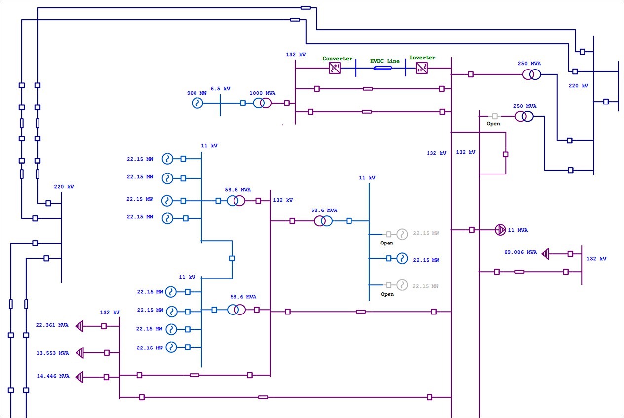
Electrical Single Line Diagram Electrical One Line Diagram Etap

Single Line Diagram Of Power System One Line Diagram Power Line Diagram Youtube
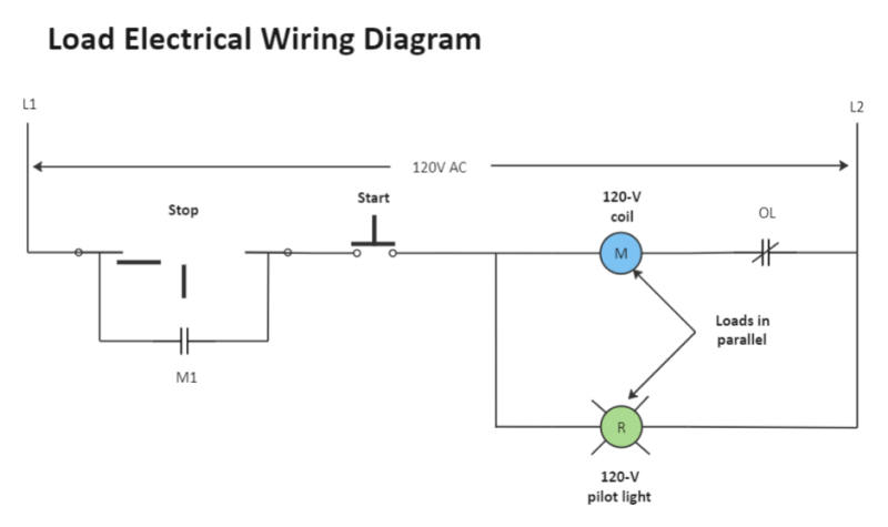
Wiring Diagram A Comprehensive Guide Edrawmax Online

Reading Single Line Diagram Line Diagram Single Line Diagram Single Line
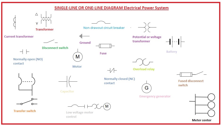
Single Line Or One Line Diagram Electrical Power System The Engineering Knowledge

Learn To Read And Understand Single Line Diagrams And Wiring Diagrams Single Line Diagram Line Diagram Learn To Read
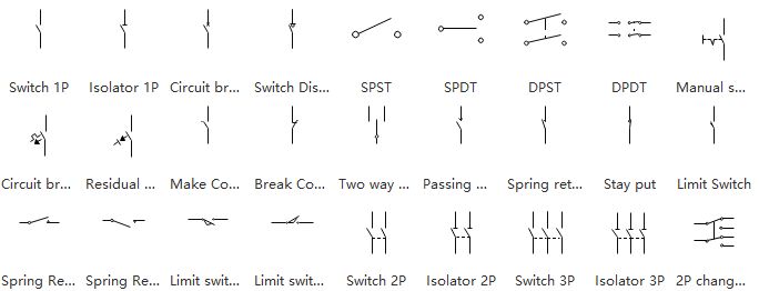
How To Read Electrical Drawing Edrawmax

A Complete Guide To Electrical Drawings And Blueprints

Single Line Diagram Inst Tools

How To Map House Electrical Circuits Home Electrical Wiring Electrical Wiring Electrical Layout

Single Line Diagram Of Power System One Line Diagram Power Line Diagram Youtube
